RS232 is a standard for serial communication. You often see it in industrial machines and network equipment. It is also in older devices. You use RS232 when you need strong communication. It works between sensors, PLCs, or barcode scanners. Many things use RS232 because it sends data in a reliable way. If you know the RS232 Datasheet, pinout, and circuit, you can use serial connections. These are in factories, checkout systems, and data monitoring. This knowledge helps you fix problems. It also helps you make communication better in many serial uses.
Key Takeaways
-
RS232 is a simple way for devices to talk. It connects things like computers, sensors, and machines. It works best over short distances.
-
Knowing about RS232 datasheets and pinouts is important. This helps you connect devices the right way. It also stops damage or mistakes in talking between devices.
-
You should use a MAX232 or a similar level shifter. This keeps microcontrollers safe when they connect to RS232 devices. Connecting them directly can hurt your electronics.
-
Pick the right cable for your devices. Use a straight-through or null-modem cable as needed. This makes sure data moves the right way and stops connection issues.
-
RS232 is still used in factories and medical devices. It is also used in old systems and DIY projects. People like it because it is easy, cheap, and works well even with noise.
RS232 Overview
What is RS232
You use RS232 when you want a strong serial link between two devices. RS232 is a standard that tells how data moves between computers and other equipment. This protocol sends signals on one wire and uses a common ground. You often find RS232 in factory machines, lab tools, and old computers.
RS232 sends data one bit at a time. It does not use a shared clock. It uses start and stop bits to mark each message. You can send data both ways at once because RS232 supports full-duplex. The protocol uses DB9 or DB25 connectors with special pinouts. RS232 uses voltages from +3V to +25V for a binary '0' and -3V to -25V for a binary '1'. Signals between -3V and +3V do not count. The longest cable is about 15 meters, but you can make it longer with special tools.
Here are the main things about RS232 serial communication protocol:
-
Uses DB9 or DB25 connectors with set pinouts
-
Lets you send and get data at the same time
-
Sends data without a clock, using start and stop bits
-
Voltage goes from +3V to +25V and -3V to -25V
-
Has control signals like RTS, CTS, DTR, and DSR
-
Cable can be up to 15 meters (50 feet) long
-
Made for speeds up to 20 kbps, but some new ones go faster
Importance Today
You may ask why RS232 is still used when there are newer protocols. RS232 is still important because it is simple and works well. Many machines in factories, labs, and hospitals use RS232 serial communication. You do not need special drivers or hard software to use RS232. This makes fixing problems much easier.
RS232 works best for short distances and slow speeds. You can connect devices up to 15 meters apart. The protocol is cheap and does not need costly parts. Many old systems still use RS232 every day. You also see RS232 in new systems that mix old and new tech.
Here are some reasons people still use RS232 now:
-
Easy to set up and fix
-
Works with many types of equipment
-
Sends data well even in tough places
-
No fees or hard settings
-
Saves money for many uses
-
Lots of help and guides from the serial communication community
💡 Tip: If you work with old or factory systems, knowing what RS232 can do helps you fix and upgrade equipment with confidence.
| Parameter | RS232 |
|---|---|
| Max Transmission Rate | Up to 20 Kbps (typical) |
| Max Cable Length | Up to 15 meters (50 feet) |
| Signaling Mode | Single-ended |
RS232 Datasheet
Key Specs
When you read an rs232 datasheet, you find key facts about how it works. The datasheet shows the electrical and timing rules you must follow. These rules help you make sure your devices can talk to each other.
Here is a table with the main specs you find in a normal rs232 datasheet:
| Specification Parameter | Typical Values / Range |
|---|---|
| Mode of Operation | Single-ended |
| Number of Devices | 1 driver, 1 receiver |
| Bus Architecture | Point-to-Point |
| Communication Mode | Full duplex |
| Maximum Cable Length | 50 feet (max data rate 20 kbps) |
| Maximum Data Rate | Up to 1 Mbps |
| Signal Type | Unbalanced |
| Mark (Binary 1) Voltage | -5 V (min) to -15 V (max) |
| Space (Binary 0) Voltage | +5 V (min) to +15 V (max) |
| Input Threshold Voltage | ±3 V |
| Impedance | 3 kΩ to 7 kΩ |
| Maximum Output Slew Rate | 30 V/µs (max) |
| Maximum Load Capacitance | 2500 pF |
| Logic Voltage Range | ±15 V, extended to ±25 V |
The rs232 datasheet tells you the voltage for logic 1 and logic 0. It also shows the longest cable you can use and the fastest data speed. If your cable is longer, you must lower the speed to keep the signal strong.
You can also look at more details in this table:
| Parameter | Conditions | Min | Max | Units |
|---|---|---|---|---|
| Driver Output Voltage (Open Circuit) | N/A | N/A | 25 | V |
| Driver Output Voltage (Loaded) | 3kΩ < RL < 7kΩ | ±5 | ±15 | V |
| Driver Output Resistance (Power Off) | -2V < V < 2V | N/A | 300 | Ω |
| Slew Rate | N/A | 4 | 30 | V/µs |
| Maximum Load Capacitance | N/A | N/A | 2500 | pF |
| Receiver Input Resistance | N/A | 3 | 7 | kΩ |
| Receiver Input Threshold (Mark, Logic 1) | N/A | -3 | N/A | V |
| Receiver Input Threshold (Space, Logic 0) | N/A | N/A | 3 | V |
The rs232 datasheet says the biggest load capacitance is 2500 pF. This limit helps stop signal loss and noise. The slew rate, which is how fast voltage changes, must be under 30 V/µs. If it goes higher, you might get mistakes.
You should also know how cable length and speed affect each other. The rs232 standard says longer cables need slower speeds. Here is a chart that shows the cable gets shorter as the speed goes up:
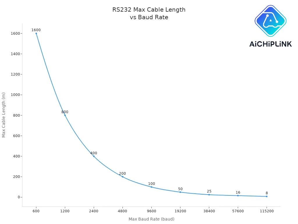
If you want to send data at 9600 baud, you can use a cable up to 100 meters. If you use 115200 baud, keep the cable under 16 meters. The datasheet helps you choose the best settings for your project.
📝 Note: Always check the rs232 datasheet for your device before you connect it. This step helps you stop damage and keeps your communication working well.
Standards
The rs232 standard is made by international groups. You find the main rules in the TIA-232-F standard. This standard tells you the voltage, timing, and connector types you must use. If you follow the standard, your devices can talk to each other without trouble.
Here is a table that shows the main rules from the rs232 standard:
| Aspect | Main Requirements |
|---|---|
| Voltage Levels | Data signals: Logic 1 (Mark) from -3V to -15V, Logic 0 (Space) from +3V to +15V. Control signals use similar ranges. Negative logic is used for data signals. |
| Maximum Slew Rate | 30 V/μsec to prevent crosstalk. |
| Line Impedance | Driver output impedance: 3Ω to 7Ω; Receiver input impedance: 3kΩ to 7kΩ. |
| Maximum Bit Rate | Standard up to 20 kbps; up to 1 Mbps for short distances. |
| Cable Length vs Baud Rate | 9600 bps supports over 1000m; 115200 bps limited to about 15m; 1 Mbps limited to 1-3m. |
| Environmental Conditions | Operating temperature from -40°C to +85°C; Storage temperature from -55°C to +125°C; Relative humidity 5% to 95% non-condensing; EMI/RFI immunity and ESD protection up to ±15kV. |
| Connectors | Use of DB9 and DB25 connectors is standard. |
| Communication Type | Point-to-point communication. Use straight-through or null modem cables based on device roles. |
The standard covers not just the electrical rules but also the connectors and cables. The rs232 datasheet follows these rules so your devices work together. The standard also sets rules for temperature and humidity, so you can use rs232 in many places.
The datasheet and the standard work together. The datasheet gives you the exact numbers for your device. The standard makes sure all devices can connect and talk. You should always check both before you start your project.
💡 Tip: If you follow the rs232 standard and use the right datasheet, you avoid most common problems in serial communication.
RS232 Pinout
Knowing the pinout of rs232 connectors helps you connect things right. This stops mistakes when devices talk to each other. There are two main connector types: DB9 and DB25. Each one has its own pinout. Both use the rs232 standard for signals.
DB9 Pinout
The DB9 connector is the most used rs232 connector now. It has 9 pins. Each pin does something special. Most new serial ports use the 9 pin rs-232 pinout. The main pins are TX (Transmit), RX (Receive), and GND (Ground). These three pins let you send and get data. Other pins help control the flow of data. They also show if a device is ready.
Here is a quick list of the DB9 pinout:
-
Pin 1: Data Carrier Detect (DCD)
-
Pin 2: Receive Data (RXD)
-
Pin 3: Transmit Data (TXD)
-
Pin 4: Data Terminal Ready (DTR)
-
Pin 5: Signal Ground (GND)
-
Pin 6: Data Set Ready (DSR)
-
Pin 7: Request to Send (RTS)
-
Pin 8: Clear to Send (CTS)
-
Pin 9: Ring Indicator (RI)
You only need TX, RX, and GND for simple jobs. For machines in factories, using RTS and CTS makes things work better.
DB25 Pinout
The DB25 connector is bigger and has 25 pins. You see it in old computers and some factory machines. The DB25 pinout has all the DB9 signals. It also adds more pins for extra control and timing. This connector can use main and extra channels.
Here is a summary of the DB25 pinout:
-
Pins 2 and 3: Main data lines (TXD and RXD)
-
Pins 4 and 5: Handshake signals (RTS and CTS)
-
Pin 7: Signal Ground
-
Pins 14, 16, 19, 13: Secondary data and control lines
-
Pins 15, 17, 24: Timing signals for synchronous communication
You pick the DB25 connector when you need more control or extra channels.
Pin Functions
Each pin in rs232 connectors has its own job. The main pins move data. Other pins control the flow and timing. The table below shows what each important pin does and how it helps.
| Pin Number | Signal Name | Function Description | Contribution to Communication |
|---|---|---|---|
| 2 | Transmitted Data (TxD) | Sends data from your device to another. | Lets you send information out. |
| 3 | Received Data (RxD) | Receives data from another device. | Lets you get information in. |
| 4 | Request to Send (RTS) | Tells the other device you want to send data. | Controls when you start sending data. |
| 5 | Clear to Send (CTS) | Shows you can start sending data. | Prevents data loss by managing flow. |
| 7 | Signal Ground | Provides a common ground for all signals. | Keeps signals stable and reduces noise. |
| 14, 16, 19, 13 | Secondary and timing signals | Used for extra channels and timing in advanced setups. | Supports modem management and synchronous data transfer. |
📝 Tip: Always check the pinout before you wire rs232 connectors. If you connect pins wrong, devices may not talk or could break.
You often use the max232 pinout to link microcontrollers to rs232 connectors. The max232 pinout matches the rs232 pinout. This makes it easy to change voltage levels and connect safely.
RS232 Circuit
Basic Circuit
You can make a simple RS232 circuit to link two devices. The most important wires are Transmit (Tx), Receive (Rx), and Signal Ground (GND). Connect the Tx pin from one device to the Rx pin on the other. Do the same for the other side. Make sure both ground pins are joined. This keeps the voltage steady. With this setup, both devices can send and get data.
If you need handshaking, connect the Request To Send (RTS) and Clear To Send (CTS) lines too. These lines help control when data moves. You might also use Data Terminal Ready (DTR) and Data Set Ready (DSR) for more control. If you do not use these extra lines, loop them back on each device. This stops the software from waiting forever for a signal.
📝 Tip: Always check your wiring before turning on your circuit. A wrong wire can stop things from working or even break your devices.
Here is a simple picture for a normal RS232 circuit:
Device 1 (DB9)         Device 2 (DB9)
----------------       ----------------
Pin 2 (Rx)   <-------- Pin 3 (Tx)
Pin 3 (Tx)   --------> Pin 2 (Rx)
Pin 5 (GND)  --------> Pin 5 (GND)
This wiring works for most RS232 jobs. You can add more wires for handshaking if your devices need them.
Level Shifting
RS232 circuits use special voltages to send data. Logic 1 uses between -15V and -3V. Logic 0 uses between +3V and +15V. Most RS232 cables use about ±12V. These high voltages keep the signal strong, even with long wires. The driver circuits in your devices make these voltages.
| Logical State | Voltage Range (V) |
|---|---|
| 0 (binary 0) | +3 to +25 |
| 1 (binary 1) | -3 to -25 |
Modern microcontrollers use much lower voltages, like 3.3V or 5V. You cannot connect them straight to RS232 circuits. You need a level shifter or converter to change the voltage. The MAX232 circuit is the most common way to do this. This chip uses a charge pump and four outside capacitors to make the high voltages for RS232. The MAX232 circuit also flips the logic, which RS232 needs.
Other level shifters, like MOSFET circuits or chips such as TXS0108E, work for normal logic level shifting. But they do not support the flipped and two-way signals of RS232. Always use a real RS232 converter like the MAX232 circuit for safe and good communication.
💡 Note: Never connect a microcontroller straight to RS232 lines. The high voltage can hurt your chip. Always use a level shifter or converter.
Microcontroller Interface
You can connect microcontrollers to RS232 devices with a MAX232 circuit. The microcontroller's UART pins (TX and RX) go to the TTL side of the MAX232. The MAX232 circuit changes the 0-5V logic to the ±12V RS232 levels. It also flips the signals as needed. The MAX232 uses four 1uF capacitors for its charge pump. You only need one +5V power supply for the MAX232 and your microcontroller.
Here is a step-by-step guide to connect a microcontroller with RS232:
-
Connect the microcontroller's TX pin to the T1IN pin on the MAX232.
-
Connect the microcontroller's RX pin to the R1OUT pin on the MAX232.
-
Attach four 1uF capacitors to the charge pump pins (C1+, C1-, C2+, C2-).
-
Connect the MAX232's RS232 output pins (T1OUT, R1IN) to the RS232 device.
-
Make sure all grounds are joined.
This setup lets your microcontroller talk to computers, modems, or other RS232 devices. You do not need two power supplies. The MAX232 circuit does all the voltage changing and signal flipping.
⚡ Alert: Putting the capacitors in the right place is very important for the MAX232 circuit. If you skip or put a capacitor in the wrong spot, the voltage change will not work, and the circuit will fail.
Cable Types and Handshaking
You must pick the right cable for your RS232 setup. There are two main types: straight-through and null-modem cables.
| Aspect | Straight-Through Cable | Null-Modem Cable (Crossover) |
|---|---|---|
| Wiring | Pinouts are the same on both ends; transmit (TxD) and receive (RxD) lines are not crossed. | Transmit (TxD) and receive (RxD) lines are crossed (for example, TxD to RxD and the other way). Extra handshake wires like RTS to CTS and DSR to DTR are often crossed too. |
| Application | Connects a DTE device (like a PC) to a DCE device (like a modem). | Connects two DTE devices directly (like two computers) without a modem or other device. |
| Communication | Both ends use the same pins, so both can 'talk' at once, which is not good for direct DTE-to-DTE links. | Crossing pins lets both sides talk and listen, so two DTE devices can talk to each other. |
Straight-through cables connect each pin to the same pin on the other end. You use these to connect a computer to a modem. Null-modem cables cross the send and receive wires. You use these to connect two computers or two microcontrollers directly.
Handshaking wires like RTS, CTS, DTR, and DSR help control the flow of data. They stop data loss and make sure both devices are ready before sending. You should connect these wires if your devices use hardware flow control.
📝 Tip: Always check your device manuals to see if you need handshaking. For simple jobs, you may only need TX, RX, and GND.
MAX232 IC
MAX232 Datasheet
You often use the max232 ic when you need to connect a microcontroller to an RS232 device. The max232 datasheet gives you all the important details about this chip. You find that the max232 ic works as a level converter between TTL/CMOS logic and RS232 voltage levels. It supports two drivers and two receivers, so you can send and receive data at the same time. The chip runs on a 5V supply and uses about 8mA of current. You can use it at speeds up to 120 kbit/s. The max232 datasheet also shows that the chip can handle input voltages up to ±30V and works in temperatures up to 150°C.
Here is a quick look at the main features from the max232 datasheet:
| Feature / Specification | Description |
|---|---|
| Function | TTL/CMOS to RS232 level converter IC |
| Drivers/Receivers | Dual drivers and receivers |
| Operating Voltage | 5V typical |
| Operating Speed | Up to 120 kbit/s |
| Input Voltage Tolerance | ±30V |
| Operating Current | 8mA |
| Package Types | 16-pin PDIP, SOIC, SOP |
| Operating Temperature | Up to 150°C |
| Internal Charge Pump | Needs external capacitors |
| Applications | Microcontroller to RS232 device interface |
You find the max232 ic in many packages, such as SOIC, PDIP, and SOP. The chip uses four 1.0 µF capacitors for its charge pump. You can use the max232 ic to connect microcontrollers to PCs, modems, or terminals.
How MAX232 Works
The max232 ic changes the voltage levels between TTL logic and RS232 signals. Your microcontroller uses TTL logic, which means 0V for logic 0 and 5V for logic 1. RS232 devices use much higher voltages. The max232 ic takes a TTL logic 0 and turns it into a voltage between +3V and +15V. It takes a TTL logic 1 and turns it into a voltage between -3V and -15V. This lets your microcontroller talk to RS232 devices safely.
Inside the max232 ic, you find a special circuit called a charge pump. This charge pump uses four external capacitors to make the high positive and negative voltages needed for RS232. The chip has two transmitters and two receivers. These let you send and receive data at the same time. You only need a single 5V power supply for the max232 ic. The chip does all the voltage work for you.
💡 Tip: Always connect the external capacitors as shown in the max232 datasheet. If you miss a capacitor, the chip will not work right.
MAX232 vs MAX3232
You may wonder if you should use the max232 ic or the MAX3232. Both chips do the same job, but they work with different voltage ranges. The max232 ic only works with 5V systems. The MAX3232 works with both 3.3V and 5V systems. If you use a modern microcontroller that runs at 3.3V, the MAX3232 is a better choice.
Here is a table to help you compare:
| Feature | MAX232 (this IC) | MAX3232 |
|---|---|---|
| Voltage Range | 5V only | 3.3V to 5.5V |
| Logic Level Support | TTL/CMOS at 5V | TTL/CMOS at 3.3V and 5V |
| Power Consumption | 8mA | About 0.3mA |
| Application | 5V microcontrollers | 3.3V or 5V microcontrollers |
| Use Case | Legacy and standard RS232 | Low-power, modern systems |
You should use the max232 ic for classic 5V microcontroller projects. If you need to work with lower voltages or want to save power, the MAX3232 is the better pick.
RS232 Equivalents
Alternative ICs
There are many ways to do RS232 level conversion besides the MAX232. Some people use USB-to-TTL cables. These cables are easy to use and do not need two-way level shifting. But, you still need the right level converter for real RS232 signals. Simple resistor dividers do not work because RS232 uses much higher voltages.
Here are some other choices you can use instead of the MAX232:
-
Transistor-based circuits use regular transistors and resistors. These are cheap and work for simple RS232 level shifting.
-
Logic gate circuits use chips like CD4066B, NAND, or NOR gates. You might use these if your project already has logic gates.
-
The MAX3232 is a common replacement. It works with both 3.3V and 5V logic, so it fits mixed-voltage systems.
-
The FT232RL is another popular choice. It changes RS232 to TTL and works in many projects.
-
RS232 modules and adapter cables can also be used. These are simple to use and often come ready to plug in.
⚠️ Note: Cheaper options may not be as reliable or block noise as well as the MAX232. Always check if your project needs a strong and safe solution.
Other Serial Standards
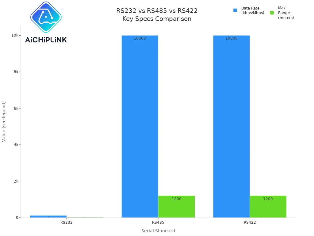
Sometimes you need a different serial standard for longer cables, faster speeds, or more devices. RS232 only connects two devices. Other standards like RS422 and RS485 have more features. They use differential signaling, which helps stop noise and lets you use longer cables.
Here is a table to compare RS232 with other serial standards:
| Feature | RS-232 | RS-422 | RS-485 |
|---|---|---|---|
| Electrical Characteristics | Single-ended signaling, uses one wire and ground, voltage is usually -15V to +15V | Differential signaling, uses two wires with opposite voltages, voltage is usually -6V to +6V | Differential signaling, lets many devices share one bus, voltage is usually -6V to +6V |
| Signaling Method | Single-ended (voltage compared to ground) | Differential (voltage between two wires) | Differential with many devices on one line |
| Transmission Distance | Up to about 50 feet (15 meters) | Can go up to 4000 feet (1200 meters) | Also up to 4000 feet (1200 meters), good for long distances with many devices |
| Applications | Connects one computer to one device | Used in factories and long serial links | Used in factory control, building systems, and long-distance links with many devices |
Each standard is good for different jobs. RS232 is easy and works for short cables. RS422 and RS485 are better for long cables and places with lots of noise. You often see these in factories, building controls, and phone systems.
Pick the standard or replacement that matches what you need. If you want something simple and that works with many things, RS232 is a good pick. If you need to connect lots of devices or send data far, try RS485 or RS422. Each choice helps you solve different problems in serial communication.
Applications
Industrial Use
You find rs232 in many factory jobs. This serial standard helps control machines and collect data. It also connects devices in factories. You use rs232 connectors to link sensors, PLCs, and computers. The communication stays strong, even in hard places. Here is a table with some common factory uses:
| Industrial Application | Description |
|---|---|
| Industrial Automation Systems | Controls robots and machines, giving real-time feedback and control. |
| Data Acquisition and Control | Connects sensors for checking temperature, humidity, and other things. |
| Networking RS-232 Devices | Links computers, sensors, and machines in a chain, making it easy to add more. |
| Manufacturing | Helps machines talk and keeps quality high. |
| Telecommunications | Works with modems and switches to move data. |
You use rs232 because it is easy and cheap. The connectors are simple to get and put in. These uses help keep factories working well.
Medical Devices
Medical devices need safe and steady communication. Many tools for testing and watching patients use rs232 to send data. You see rs232 connectors on things like patient monitors and lab machines. This standard lets you send and get data at the same time. It also checks for mistakes, so data stays right. Medical devices that only use wires like rs232 do not need radio rules. They must follow safety and security rules for hospitals. You can trust rs232 for safe and steady data in healthcare.
Legacy Systems
You still see old systems that use rs232. These systems need serial communication for daily work. You can use rs232 emulation tools to make fake COM ports. This lets old programs talk to new hardware, even without real serial connectors. You save time and money by keeping old equipment working longer. Rs232 helps connect new and old tech. There are many guides and help for fixing and updating these systems. The simple design and low price of rs232 make it a good pick for old systems.
-
You can add rs232 to old devices.
-
You can use rs232 to link new computers to old equipment.
-
You can spend less on repairs by using easy serial communication.
DIY Projects
You can try many DIY projects with rs232. Hobbyists build hubs to connect many devices. You might make an RS232 Serial Spy to watch data between two devices. Some projects use special UART to rs232 modules to protect electronics. These projects help you learn about serial communication and connectors. There are many groups online sharing plans and tips. If you like building things, rs232 is a simple way to start your own projects.
-
Build an rs232 hub to manage many devices.
-
Make a serial spy tool to watch data move.
-
Design a safe UART to rs232 module for better protection.
💡 Tip: You can find lots of step-by-step guides for rs232 DIY projects on electronics forums and maker websites.
RS232 is still used today and in old systems because it is easy to use, works well, and does not cost much. You can use RS232 in loud places with lots of electrical noise. It lets you connect different kinds of devices. If you know how to read datasheets, pinouts, and circuits, you can fix problems quickly and make better designs.
-
RS232 lets you send and get data at the same time. It uses simple voltage rules and is good for one-to-one connections.
-
Learning about start, stop, and parity bits helps you stop mistakes and keep your data safe.
📚 If you want to learn more, look at datasheets for MAX232 ICs and read guides about RS232 standards, pinouts, and how people use it in real life.
FAQ
What devices can you connect with RS232?
You can connect computers, microcontrollers, PLCs, barcode scanners, and lab equipment. Many old printers and modems also use RS232. You often see RS232 in factories and hospitals.
How do you know if your cable is straight-through or null-modem?
Check the wiring. In a straight-through cable, pin 2 connects to pin 2 and pin 3 to pin 3. In a null-modem cable, pin 2 connects to pin 3 and pin 3 to pin 2.
Why does RS232 use negative voltages?
RS232 uses negative voltages to help reduce noise and signal errors. The negative voltage makes the signal stronger over longer cables. This helps keep your data safe.
What should you do if your RS232 connection does not work?
🛠️ Tip:
Check your wiring first. Make sure TX connects to RX and grounds match. Try a different cable. Check your baud rate and settings. If you still have trouble, use a MAX232 or similar converter.

Written by Jack Elliott from AIChipLink.
AIChipLink, one of the fastest-growing global independent electronic components distributors in the world, offers millions of products from thousands of manufacturers, and many of our in-stock parts is available to ship same day.
We mainly source and distribute integrated circuit (IC) products of brands such as Broadcom, Microchip, Texas Instruments, Infineon, NXP, Analog Devices, Qualcomm, Intel, etc., which are widely used in communication & network, telecom, industrial control, new energy and automotive electronics.
Empowered by AI, Linked to the Future. Get started on AIChipLink.com and submit your RFQ online today!